Thursday, 9 February 2012

Brazing the Front Forks

As promised last time, I've been directing my efforts at getting the front forks brazed up. There seemed to be an endless list of things to do before I could light up the oxy-acetylene though. I needed to hollow out the stubs that extend into each of the tubes. As mentioned before this is for several reason, firstly it helps to prevent cracks forming at the junction of the stub and the tube. Secondly it makes the brazing process easier as a large mass of material that is hard to heat is removed, this helps to prevent overcooking the tubes. And last is the obvious weigh loss from removing metal. In this case, hollowing out the 6 stubs (2 per 'knee' and 2 on the head) removed a pound of weight (0.45kg). Not insignificant.

However before I hollow out the stubs, I need to stamp the top of the Abingdon Ball Head with the appropriate patent information. I need the stubs to be solid to support the hammer blows required to do this. I admit to putting this task off for ages, the potential to completely screw it up is high. Every now and again I'd have a little practise on some scrap until I had developed a method of working that reduced the chance of errors. I was still shaking when I struck every letter and number though. The hard bit is to get the individual letters to be correctly aligned vertically with respect to each other and correctly spaced. My method is simple, I use 4 layers of masking tape to define the lower edge of each letter or number, placing each stamp onto the surface of the workpiece and then sliding until it contacts the ridge of masking tape. With practise, it becomes easier to apply the same pressure against the tape and the letters then line up with each other. To get the spacing correct, I mark the tape ridge at the correct intervals and then line up each stamp with the next mark.

It is worth noting that letters or numbers with less area, such as I and 1, require a lighter blow
 other wise they appear over struck compared to larger letters.

The results aren't too bad although the I is too far to the right,
I'm not too bothered as the original is also clearly hand stamped.

With this onerous chore out of the way I can now hollow out the stubs. I very roughly drilled and milled out as much material as possible before getting stuck in with a carbide burr mounted in an air die grinder. I bought a cheap Chinese die grinder that will run at 25,000 rpm without over running my compressor too much. Think of a dentist's drill on steroids. You really do need those high rpms when removing steel. It is a truly horrible job and results in thousands and thousands of razor sharp needles of steel *everywhere*, regardless of how carefully everything else is covered up. I've been digging steel splinters out of my fingers (and feet!) ever since despite wearing a ridiculous amount of PPE.

Roughly removing as much material as possible...

...before getting the carbide burr out


A pound of steel was removed from these 6 stubs.

Now I need to make a jig to hold everything in the correct location whilst the heat is applied.

I happened to have some angle iron in my magic cupboard, so this got chopped up... 

...and with some 10mm threaded rod, I can locate all the bits in a frame that doesn't move.

I used 40% silver solder to keep the heat on the 4130 chromoly tubing down. Silver solder has suddenly got really expensive, still I only need the one kidney. It all appears to have been successful with good penetration into the joints and very little distortion from the heat, although one of the blanks in the bearing house was *very* hard to get out afterwards. Fortunately I had previously made a 1.75" x 26tpi tap and had it hardened for exactly this eventuality and I was able to clean out the threads nicely.

This week I'll clean up the joints and mill the slots for the locking tabs. Then I can continue with the gunmetal flanges. Then I can make the spokes... etc. I've set myself a goal of having the frame sat on it's wheels inside of a year. I'm already 6 months into the project and more or less on track.

In other news, I've finally managed to arrange a small aftershock for my parents, We were having dinner in Christchurch and were rudely interrupted by a vicious little 4.6, I don't think they liked it much. We also had a nasty little swarm last night but fortunately my parents are away on a tiki tour of the West Coast this week. I'll try and save a few for their return.

In more other news, someone seems to have stolen summer this year. We haven't had one yet, does anyone know where it is?

Saturday, 28 January 2012

Harden the four cup(s) *

I've been able to get out in the shed a little this week. Enough to fettle the rear hub from a bar of 4140. When I checked the drawings I had made back in 2008, I was certain that I'd made a mistake measuring the original and that I'd got the dimensions too small. I even checked a couple of 1890's front wheels I have lying around which confirmed that the measurements were correct. The bearings seemed tiny when compared with the large front wheel bearings, but are exactly comparable with a modern front wheel.

The first task is to make the hub shell, this uses the same techniques as in the front hub just on a smaller scale and with fewer bearing surfaces (!). There is no need to mill key ways to lock the gunmetal flanges in place since the rear hub transmits no torque. In practise I have found that the spoke tension will adequately hold the flanges in place, however I will either make them an interference fit or soft solder them on as was the norm back in the day. The oiler hole is tapped at 2BA, I'm happy using BA threads since they were first formulated in the 1880's and I have previously found them on antique bikes.

The next job is to make the cones, the fixed (right) cone is left smooth but the adjustable (left) cone is knurled with a straight, fine pattern. My knurling tool has diamond pattern wheels and with the shocking local price of replacement wheels, I've milled 80 'knurls' instead of rolling them.

Roughing out one of the cones

Parting it off.

Machining the outside face.

Milling the 'knurls'

The hub spins beautifully on it's 11 x 3/16" balls in either race. 

I've calculated a formula for the dimensions of the race based upon the number and size of balls required, this has worked out well so far although the formula leaves no room for a gap in the balls which they need. You can either add one to the number of balls (n) or just add a smidgeon to the calculated value D. I have found that making D larger by 0.020" or so is enough to get a useful gap. The calculated value for D in the rear hub = 0.1875/sin(180/11) + 0.1875 = 0.853". In practise I machined it to 0.875" and have a sufficient gap, as can be seen in the above photo, so the balls don't bind.


With all the steel components of the hubs now complete, I can get them heat treated. I initially chose 4140 steel because of it's suitability for nitriding which produces a very hard surface case up to Rc 64 but retains the tough centre. Nitriding will also cause far less distortion due to the lower heat required. SSM have a local office so I gave them a ring in the morning and was told that if I can get the parts to them by 10 o'clock they could put them in today's batch and I could pick them up in the afternoon. A fantastic service, I'm sure you'll agree.

The parts were still warm when I picked them up, 
like fresh hot cross buns straight out of the oven, only not as tasty. 
And a bit harder.

In other news my parents are now here and are pleased that I've been unable to organise any large aftershocks so far. My Dad is being kind to me and has only offered advice on using the dividing head to date. He sits on the stool in the corner of the workshop like a benevolent owl. I'm going to try and get the forks brazed up whilst he's here. He has far more experience than me at brazing, so I'll get him to do it and then I can examine his work. This will be the focus of my shed time next week.

We had a huge electrical storm at the weekend, It passed directly over our house and we suffered a very close lightening strike. Had I any hair remaining I'm certain it would have stood on end from the electrickery. My wife's new computer (birthday present) had it's motherboard fried and we are trying to arrange a repair on insurance. What fun. In the meantime I've resurrected an ancient steam powered computer to allow us to access the interweb and me to continue posting this nonsense.

* with apologies to Chopper Reid

Wednesday, 18 January 2012

The Front Hub

I've spent a little time this week making the front hub for the facile. This is a complicated affair and has 6 bearing surfaces that must all be concentric. It is hollow and has several holes and ramps that all need to accurately located. Lots of 4 jaw and fixed steady use.

Once again a series of photos to illustrate the various processes, click for larger versions.

Centre the ends, machine a plain surface to use the fixed
steady on and bore a pilot from either end. The pilot holes
met accurately (not too easy with a 7" bar)
Cut the first pair of bearing surfaces,
the end of the hub is also now at final size.
Now enlarge the bore to final size from this end.
Then machine the inner bearing race and clean up the bore,
These three bearing surface are now all concentric.
Now flip the hub around and repeat on the other end.
The centre section needs to be thinned to size.
Like this.
Then all that's left is to drill the holes to poke the balls through,
mill the key ways to lock the gunmetal flanges...
... and mill the angled ramp that is used to lock the sun gear to the  hub.
Finally after all that I can trial a fit up with all the parts assembled.
The hub spins beautifully on it's 60(!) balls.


In other news, my parents are arriving for an extended holiday with us. This has meant a flurry of activity around the house. The workshop has been tidied, the garden weeded, the lawn cut and the children polished. I only hope that the work so far on the geared facile bears Dad's scrutiny. I just know he'll be out fiddling with stuff whilst I'm at work. I'll have a word with Mum.

I reported last time that I didn't feel the magnitude 6.0 aftershock as I was riding home at the time. It appears that I did feel it, I just didn't realise it. On the way home I had caught up with a mate of mine, another local cyclist, at a set of traffic lights. Matt has a new fangled bike computer that does GPS stuff as well as speed etc.  I'm a retrogrouch and only need a calendar to calculate my average speed these days. This means that given the exact time of the 6.0 from geonet, he was able to work out very accurately where we were at the time. At the spot in question we were almost home and on a very wide straight road so we were riding two abreast and chatting. I remember that very suddenly we clipped handlebars for no reason, I dismissed it as either Matt, myself or both of us being a crap cyclist. Now Matt's a handy rider so that just left me. I'm just glad that my ego is intact.

Friday, 6 January 2012

Smells like Dads

Now then, where did we get to? Oh yes, I'd machined the bearings for the front hub. Unfortunately at this point we had another earthquake swarm, we took a holiday and my wife fell off her bike so I haven't updated you for a while. Near normality has now been resumed.

The outer bearing races need the castellations machining. These act as the locking points for fine tuning the bearing adjustment. There are 35 such castellations and combined with a 26 tpi thread means that advancing one notch adjusts the bearing clearance by 1/910th of an inch. The castellations are machined at a 45 degree angle so that the locking tab, also machined at the same angle will sit flush in it's locating groove. More later.

Holding each race to machine these notches proved tricky, I initially tried to grip the threaded area in a three jaw chuck, protecting the threads with a soft copper strip. This approach proved unsatisfactory on so many points that I quickly gave it up. The machining tended to pull the workpiece from the chuck and clearance was not possible where the jaws gripped. Also three jaw chucks aren't accurate enough to properly centre the workpiece for the tolerances I wanted. So I needed to made a one off chuck to hold the races. First I machined the thread to screw the chuck directly to the Myford's register, the Myford nose has a 1.125" X 12 tpi thread. Then with the new chuck mounted onto the nose I could machine the internal thread to hold the bearing race, this has the advantage that I am guaranteed that both threads are concentric and hence that the race will be held perfectly concentrically. I also need to bevel the outer edge to allow clearance for the slitting saw to cut the grooves.

This new chuck can then be mounted on the Myford dividing head (same thread and register) and the setup as per the following photo. 

Indexing the castellations with the dividing head mounted on a swivelling slide mounted on a fixed slide.

The cuts are made in one pass at full depth, the depth being advanced with the cross slide and the cut being fed with the fixed vertical slide. The swivelling vertical slide is locked in place with it's gib strips, in fact every slide not in use was locked to maximise rigidity on such a contrived setup. Also note that I needed to make an arbor for the slitting saw to use between centres. I did buy a cheap Chinese arbor that was so eccentric that it was unusable, the saw was only cutting on a few teeth at a time rather than all of them, this caused massive vibrations and chatter and much anxiety. Just goes to prove that you get what you pay for I guess. I had intended to put a grub screw and a copper disc at the bottom (same as myford does when locking a grub screw on a thread) into the body of the chuck to secure the races but I found this was unnecessary. I simply placed a rubber sheet on the bench and the race screwed into the chuck onto this, then applying downwards pressure whilst turning I could tighten or loosen the race from the chuck, the rubber gripping the race to allow it to be tightened securely. The actual machining took just a few minutes per race whilst making the chuck, the arbor and the setup took many hours. I'm pleased with the results though.

The next component to be made is the hub that rotates in these races. First though, I need to machine a test piece to ensure that I have the clearances correctly calculated. The design of the bearing is such that the balls are loaded by inserting them up through a hole into the middle of the bearing. The placement of this hole is critical and only has a 5 thou margin of error. Too close to the outer race will impinge on the bearing surface and too close to the centre will not give clearance for the balls to be inserted past the lower flange of the race.

When I was measuring the original machine, I wondered what this hole was for. It's only as I came to draw up the bearing design that I realised that it can't be assembled without it.

 
Here's one I made earlier.

The complete bearing is loaded as follows

Screw both races into the bearing housing, the inner race in it's correct location and the outer race fully screwed in up against the inner race.

Load 15 X 1/4" balls into the inner race, there's plenty of clearance at this point so these can all be loaded from outside.

Hold the inner race up against the balls so that they don't fall out and orient the hole to be at the top.

With the outer race screwed fully in against the inner race there is just clearance (the 5 thou mentioned earlier) to poke the remaining 15 balls into the outer race through this hole.

Then screw the outer race out to make contact with the balls and lock the race with the castellations. The inner race is locked with a grub screw.

The inner row of balls is protected by a labyrinth seal partly formed by this flange.

I'll make the actual hub next week.

In other news, our festive season here has been punctuated by a series of disasters.

1) The pre Christmas revelry was rudely interrupted by another swarm of nasty aftershocks, lots of magnitude 5 somethings and one magnitude 6. I was riding home when the 6.0 struck and I didn't feel it, weird eh? We have lots more cracks in our house and the workshop was thrown around a little. I was making a final cut one morning when we had a 5.1 or so and my lovely machined surface became a seismograph, I think I'll leave it as is. Things are beginning to quieten down a little now but I've still been woken three times this week, we've had several hundred aftershocks in the two weeks since Christmas.

2) Fortunately we had a holiday booked up in the Marlborough Sounds between Christmas and new year, we were going to walk part of the Queen Charlotte Track and stay at lodges rather than camp, The drive up was in Beautiful sunshine and as we started the walk it began to rain. It rained (hard) for the next 4 days non stop but then cleared up just as we were driving home again. Nice.

3) For Christmas I'd bought each of the kids a computer for their mountain bikes, so they were keen to try them out. We were enjoying the track at McLeans Island when my wife had a small spill. Very low speed and she'd managed to get a foot down so it didn't look too bad, turns out she needed 14 stitches. Of course, we were miles from a road and the ambulance had a bit of a nightmare getting to us but the St. John dudes were fantastic, very calm, very professional. Top marks guys. You begin to realise how small the population is in NZ when sat at the side of a mountain bike track. My wife seemed to know every other person that rode past, either that or she had taught them at some point.

6 inside and 8 outside

4) And worst of all, I ran out of Swarfega. I bought some more at lunchtime and had the tub sat on my desk at work. Tinkerbell, who sits near me, commented that "Swarfega smells like Dads". She is of course, absolutely correct.

Wednesday, 14 December 2011

Bearing All

Last week I mentioned that I would take my pretty patterns to the local steel foundry. Unfortunately my foolhardy foundry foray floundered. The foundry wasn't at all interested in a small run of one offs. I still have a couple of less local options before I try even farther afield, this will all have to wait until the new year though as New Zealand stops for a month at Christmas for the summer holidays. If this fails then I'll just have to fabricate the bits from scratch rather than cast them. Sigh.

Also, I went to pick up the tubing for the backbone from my local supplier. A piece of 1 3/8" 0.049" chromoly that I ordered two months ago. It seems that my supplier isn't. I'll have to look further afield for this as well. Trying to use local companies can be too trying.

So, in the meantime I'm going to start work on the wheels as a complete break from the recent disappointments. The front hub has a most complicated arrangement of bearings, featuring a double row of balls per side and then a live axle running concentrically through the hub on a pair of bearings. The hub has 6 bearing surfaces that all have to be concentric, I'll need to plan how to machine this carefully.

However before I can start on the axle, I need to make the bearing races that screw into the bearing housings, the knees, previously made.

Starting with a lump of 4140 steel that happens to be ground at 1.75" already

Centre it carefully and cut a 26tpi thread along enough of a length so that I can make all four races without removing the work from the chuck so that the threads and the bearing surfaces are all concentric.
Checking the fit.
Bore a big hole using my fabulous new boring bar.
Rough out the bearing surface as a plain bore with a 45 degree bevel at the inner end. 

The idea is to minimise the amount of material to be removed by the form tool as much as possible. This photo is from the second bearing off the bar as I forgot to take a picture of the first one I made.

Then use a form tool to profile the bevel to a radius of the correct size.
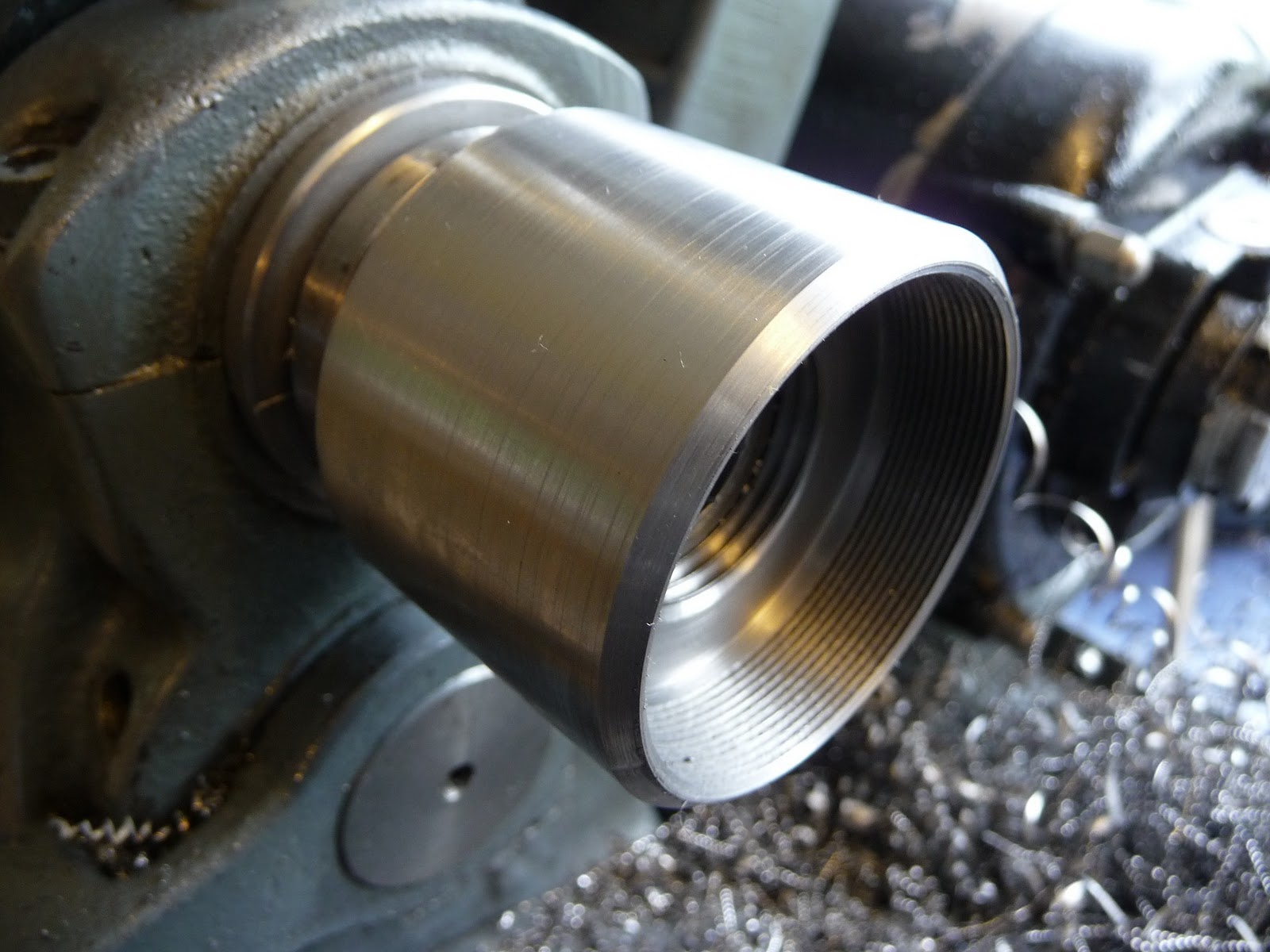
 The picture makes this look easy but in practise I had a nightmare on this job. Using a form tool on an external surface is hard enough what with all that chattering going on distracting you, but internally it all gets harder still, literally. I initially used a ground piece of HSS as my form but found that if it rubbed even a little, then the 4140 work hardened and I got extra grumpy. I had to use carbide to prevent this and slow the lathe right down. Carbide plus slow is not a normal combination, but it works really well in this application. Note that I also had to relieve the tool holder to prevent fouling on the work piece.

With the form cut I can then polish the bearing surface.
I'll need to do this again after I've had them hardened.

Then part off each bearing with enough meat left to clean up the inner, parted off, edge.

The inner races have an extra flange extending inwards, 
this forms part of a labyrinth seal with the hub flanges, more later.

I still need to machine the castellations on the outer races that allow the adjustment to be locked. I'll need to figure out a set up for that on the ever versatile Myford.

In other news, I've set up a small work bench with a vice in another part of the shed for the kids to play with. I'll get them a selection of tools for Christmas and let them cut off digits at their leisure. They don't read this blog, so I won't be spoiling any surprises.

Note that the vice is on the left, both my kids are sinister despite my wife and I being dexter. 
Weird eh?

Wednesday, 7 December 2011

Patterns

This week I've been making pretty patterns in my shed.

I use patterns most days in my job, but I don't mean that kind of pattern, I mean casting patterns. Although of course it amounts to the same, something easily repeated.

You may recall that some weeks ago I requisitioned Mr. Middleton's wood lathe to turn up the blanks from some 'donated' apple wood.

Part payment for my appalling injuries sustained whilst at Mr. Middleton's house.
I've spent a little time removing some bits and adding some more to make the final shapes. Isn't it quick to make stuff out of wood? I don't do it very often but I quite like woodworking. I often think that working with metal is digital or binary in that what you make is either right or wrong, it fits or it doesn't. Whilst wood is analogue and you need to allow for inconveniences like grain, knots and movement. Wood is a far more emotional medium. But what do I know?

I do know that I now need to clean up my workshop again as it has a pile of wood shaving instead of swarf. I think I'll bribe my children to do it for me.

Some slots to allow other bits to be firmly stuck on.
Some more bits to be stuck on. The filler to radius the corners is a two part epoxy resin.
The elliptical profile has been left oversize to allow for shrinkage and to make adjustments
 when filing to fit the  backbone. The sealer is also a two part epoxy compatible with the filler.
The paint is just an automotive primer.
I'll take these to the local foundry next week and see what they say.

In other news, last weekend was the Santa Parade here in Christchurch. The route was different this year as the traditional route has been somewhat munted by the earthquakes. We were invited to take part as usual on the antique bikes and we had a good turn out this year with quite a few younger riders which is good to see. The weather was as hot as it always seems to be for this event and the crowd was as big as usual despite the route change. An estimated 100,000 people lined the route.

This bit is actually part of my commute, Usually more cars, less people, different bike