Wednesday 29 February 2012

Spoke Flanges part 2

This week I've been drilling and tapping some holes, quite a lot of holes actually. Which in itself is an interesting question, how many spokes does a geared facile have? There doesn't seem to be an easy answer. I've conducted a survey on my own original sources which includes original photos, catalogues, adverts and machines that I know have original equipment. I've disregarded restored bicycles where I either don't know or suspect that the equipment is reproduction. Front wheels can have 50, 56 or 60 spokes with 50 being the most common, rear wheels can have 24, 28 or 30 with 30 being the most common. Also bear in mind that wheel sizes varied, with the front wheel offered in 36", 38" and 40" throughout the 5 years of manufacture, The rear wheel size varied with age, earlier bikes having a smaller rear wheel of 22", later bikes 24". I don't yet know if the rear wheel size varied with front wheel size. The machine I am copying has 40" front and 24" rear wheels with 60 spokes front and 30 spokes rear, this is a pneumatic bike though and Ellis & Co. may have felt that the new fangled tyres required a  stronger wheel. I have decided on 50 front and 30 rear, which is a common combination, it also has the advantage that both wheels have the same spoke spacing at the rim. Aesthetic reasons and all that....

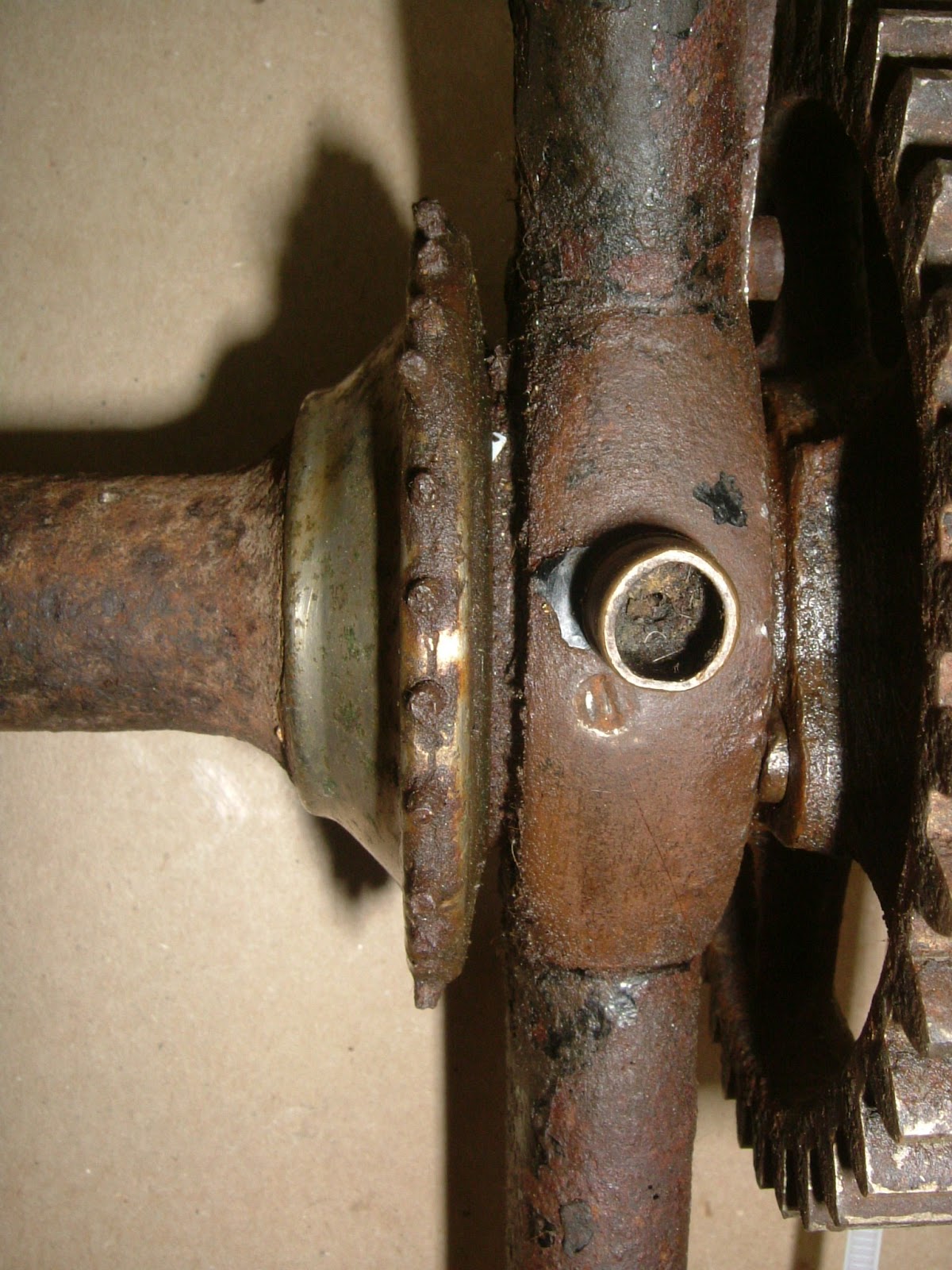
So the next question is what gauge are the spokes? Fortunately this is handily stamped on the flanges.

60 x 13 gauge spokes. 

The remains of the original spokes measured 0.093" x 56tpi they are also (fortunately) straight gauge with no butting. I have made butted spokes before but it adds a considerable amount of time to a project. So all I need to do is get some 13 gauge wire of a decent tensile strength and roll some 13 gauge threads on one end and head the other end. But what thread do I use for the tapped holes? 13 gauge spokes are a very good fit in #3x56 UNF threaded holes. For the record 14 gauge spokes are #2x56 UNC.

The first job is to make a mandrel with a keyway to securely hold the flanges whilst I drill and tap them.

I used a chunk of aluminium just because I happened to have it lying around. 

The important bit is to not take the mandrel out of the chuck after it has been turned, this ensures that the flanges will be true to the register and the holes will all be centred on the flange with no wandering. The dividing head is invaluable for the drilling and tapping operations.

First centre drill the flanges, then drill the through holes and finally tap the threads.

The second flange requires a little thought since the spokes holes must be timed correctly relative to the first flange, spoke holes falling between opposite spoke holes and all that. I've been indexing at 1/25 of a circle for the holes, so If I advance 1/50 and then continue at 1/25 this will all work out.

The rear wheel flanges were easier when I realised that I didn't need to make a mandrel at all since these flanges are not keyed and the holes are aligned at the time of assembly.

First bore through for the cones and then cut the mounting recess 
and the inner profile. I've tried to catch the shower of chips 
that comes off when machining gunmetal, it really is spectacular.

At this point I can remove the chuck with the work still 
mounted and remount on the Myford dividing head and drill...

 ...and tap the holes as for the rear wheel.

Then remount in the lathe and cut the outer profile and part off.


Next week I'll polish and nickel plate all of the hub components made so far at which point I can then think about rims.

In other news, today is the last day of summer. We haven't had much of a summer at all really and the mornings are decidedly cooler and definately darker. The commute this morning was quite chilly.

My daughter celebrated her birthday on Sunday, she invited a gaggle of school friends to come around and practice make up and do some shouting and other such stuff. My son and I decided to go out for the evening and watch one of the star wars films in 3D which was wasome. He wants me to make a podracer in my shed next. I bet they don't use 13 gauge spokes.

Wednesday 22 February 2012

Front Wheel Spoke Flanges - part 1

Well I was wrong, it turns out that you can cold set 4130 tubes. You just need a long enough lever. The bearing housings are now almost perfectly aligned and even though the original error was small, it would have bothered me. I'm like that.

So this week I've been making a pile of very expensive swarf chips by machining a large chunk of gunmetal into slightly smaller spoke flanges. As I expected the gunmetal machines beautifully. At one point, when I was removing a large volume quickly, I had a fountain of chips spraying off. Unfortunately, I was machining in short sleeves and lightly toasted my left arm.

Starting with this billet, amongst other things, I made some...

...very expensive chips.

The first step is to thin the billet down to the correct outer dimension 
and bore the centre deep enough to make two flanges at one chucking.

Aside from my own measurements of originals it is interesting to compare
against the actual specifications from the literature of the time.
This is from 1887, a few years earlier than the original I am copying.

Next step is to bore the recess for the inner bearing race, this is the final part of the
labyrinth seal. Also face the outer edge of the flange at the correct spoke angle.

Then I needed to machine the inner profile of the flange, 
this had to be done carefully to be an accurate facsimile of the original. 
Also round off the top of the flange and machine a groove to locate
 the spoke holes in the centre. Finally part off and make the twin flange.

Next job is to remount each flange the other way around and 
bore the slight recess for the hub and round off the shoulder.

And finally, I get the opportunity to use the keyway 
slotter that I bought years ago and have never used.

The completed flanges with a length of key steel used to lock them to the hub.

I'm pleased with the appearance compared with the original.

Next week I'll drill and tap the spoke holes.

In other news, we have much sadness now that my parents have gone home. To take our minds off this we accepted an invitation to a veteran car event here in Christchurch. We had a decent 50km ride on the Saturday which was hard on the way out and then tailwind home, magic. The following day we assembled in the Botanical Gardens in period costume and had a posh picnic. Several members couldn't resist showing off for the tourists and performed penny farthing trick riding on one of the lawns. My Son was over the moon when he was offered a ride in an 1899 steam Locomobile in beautiful condition.

Wednesday 15 February 2012

Bearing Adjustment Locks

Cleaned up silver soldered joints, the head will be plated later
and these require a little more work.

I've not had a huge amount of shed time this week although I have been able to clean up the brazed joints and make the little locking tabs for the bearing adjustment. These locate in grooves milled into the upper fork legs at the appropriate angle and width.

The depth is not super critical but I didn't want to
break through the tube wall so I had to be careful here.

The brazed joints all cleaned up easily but doing so showed up a slight movement in the non gear side bearing housing. This has clearly happened as a result of the heat, the housing are now not quite parallel. The discrepancy is very slight and doesn't seem to affect the bearing (I built it up to check) which is good because the chances of cold setting the 4130 forks is effectively nil, they are very strong.

I also drilled and tapped the holes for the oiler and inner bearing race locking grub screw (2BA & 4BA respectively). On the original these holes were very close. too close I thought so I cross referenced with some pictures I took of the racer in the Coventry Transport Museum. This famous machine has the oiler hole located much higher up and away from the grub screw, I have done the same and based mine upon the Percy Nix bike in Coventry.

The original facile I am copying has very close
holes for the oiler and inner race grub screw.

The holes on Percy Nix's racing machine are farther apart.

I've based mine upon the Coventry machine.

A good view of the grub screw and the oiler in place. 
The Coventry bike is missing it's oilers, this oiler is missing it's cover.

The locking tabs are asymmetric in that the one on the gear side is longer than the non gear side, this is so that the bearing can still be adjusted with out removing the gear from the hub. I did consider machining them but decided that the set up would take longer than careful hand filing.

They're tricky little things, the inner edge is a curved 45 degree bevel 
and then two notched are filed into this to produce three teeth 
to lock into the castellations on the outer bearing race.

My stock of 4BA cheese head screws is a little low, 
hence the rusty one used in the picture.
 BA screws are all but unobtainable for sensible money in NZ 
so I'll either make or import some myself.

Next week I'll hack into a large chunk of Gunmetal (LG2 bronze) and start the spoke flanges for both wheels. Gunmetal machines beautifully so I'm really looking forward to this.

In other news my parents, both keen gardeners, have been busy in our garden. When we moved in many years ago we found an old greenhouse hidden in one corner of the garden. My parents have now dismantled this to allow us to move the compost bin to somewhere where it may actually work. My father has about a dozen greenhouses himself but I'm unsure how he's going to fit mine into his suitcase when he leaves. I'm sure he'll try.

An amusing incident happened at dinner the other night, the children were running through all the languages that they knew how to say hello in. After the obvious English, French, German, Spanish, Maori & Japanese, my daughter upped the ante with Gaelic. "Pogue Mahone" she proudly said. I nearly spat my tea all over the table, having shared a house with a native Gaelic speaker at University I happened to know what this very useful phrase actually means. I suspect that an unknown Irishman has been having a little fun at the expense of my Daughters teacher. Apparently the class all solemnly repeat the phrase in that special monotone that children the world over reserve for "Good Morning Teacher". My daughter was very embarrassed when I told her what it meant, whilst my son was busy writing it down. My parents were not amused in that very Victorian manner.

Thursday 9 February 2012

Brazing the Front Forks

As promised last time, I've been directing my efforts at getting the front forks brazed up. There seemed to be an endless list of things to do before I could light up the oxy-acetylene though. I needed to hollow out the stubs that extend into each of the tubes. As mentioned before this is for several reason, firstly it helps to prevent cracks forming at the junction of the stub and the tube. Secondly it makes the brazing process easier as a large mass of material that is hard to heat is removed, this helps to prevent overcooking the tubes. And last is the obvious weigh loss from removing metal. In this case, hollowing out the 6 stubs (2 per 'knee' and 2 on the head) removed a pound of weight (0.45kg). Not insignificant.

However before I hollow out the stubs, I need to stamp the top of the Abingdon Ball Head with the appropriate patent information. I need the stubs to be solid to support the hammer blows required to do this. I admit to putting this task off for ages, the potential to completely screw it up is high. Every now and again I'd have a little practise on some scrap until I had developed a method of working that reduced the chance of errors. I was still shaking when I struck every letter and number though. The hard bit is to get the individual letters to be correctly aligned vertically with respect to each other and correctly spaced. My method is simple, I use 4 layers of masking tape to define the lower edge of each letter or number, placing each stamp onto the surface of the workpiece and then sliding until it contacts the ridge of masking tape. With practise, it becomes easier to apply the same pressure against the tape and the letters then line up with each other. To get the spacing correct, I mark the tape ridge at the correct intervals and then line up each stamp with the next mark.

It is worth noting that letters or numbers with less area, such as I and 1, require a lighter blow
 other wise they appear over struck compared to larger letters.

The results aren't too bad although the I is too far to the right,
I'm not too bothered as the original is also clearly hand stamped.

With this onerous chore out of the way I can now hollow out the stubs. I very roughly drilled and milled out as much material as possible before getting stuck in with a carbide burr mounted in an air die grinder. I bought a cheap Chinese die grinder that will run at 25,000 rpm without over running my compressor too much. Think of a dentist's drill on steroids. You really do need those high rpms when removing steel. It is a truly horrible job and results in thousands and thousands of razor sharp needles of steel *everywhere*, regardless of how carefully everything else is covered up. I've been digging steel splinters out of my fingers (and feet!) ever since despite wearing a ridiculous amount of PPE.

Roughly removing as much material as possible...

...before getting the carbide burr out


A pound of steel was removed from these 6 stubs.

Now I need to make a jig to hold everything in the correct location whilst the heat is applied.

I happened to have some angle iron in my magic cupboard, so this got chopped up... 

...and with some 10mm threaded rod, I can locate all the bits in a frame that doesn't move.

I used 40% silver solder to keep the heat on the 4130 chromoly tubing down. Silver solder has suddenly got really expensive, still I only need the one kidney. It all appears to have been successful with good penetration into the joints and very little distortion from the heat, although one of the blanks in the bearing house was *very* hard to get out afterwards. Fortunately I had previously made a 1.75" x 26tpi tap and had it hardened for exactly this eventuality and I was able to clean out the threads nicely.

This week I'll clean up the joints and mill the slots for the locking tabs. Then I can continue with the gunmetal flanges. Then I can make the spokes... etc. I've set myself a goal of having the frame sat on it's wheels inside of a year. I'm already 6 months into the project and more or less on track.

In other news, I've finally managed to arrange a small aftershock for my parents, We were having dinner in Christchurch and were rudely interrupted by a vicious little 4.6, I don't think they liked it much. We also had a nasty little swarm last night but fortunately my parents are away on a tiki tour of the West Coast this week. I'll try and save a few for their return.

In more other news, someone seems to have stolen summer this year. We haven't had one yet, does anyone know where it is?