Showing posts with label brazing. Show all posts
Wednesday, 9 January 2013
It all comes together
As mentioned last time, I wanted to get all the outstanding brazing work completed before I went back to work in the new year. I'm now back at work but I'm pleased to say that I did manage to find half a day to go and hire the oxyacetylene and get the bits stuck together.
I'd accumulated quite a pile of bits ready for brazing and it was good to get them all attached to each other at last. There are 5 sub assemblies to be brazed:
The new bolts into the cantle plate.
The bolts into the spring carrier
The saddle post clamp
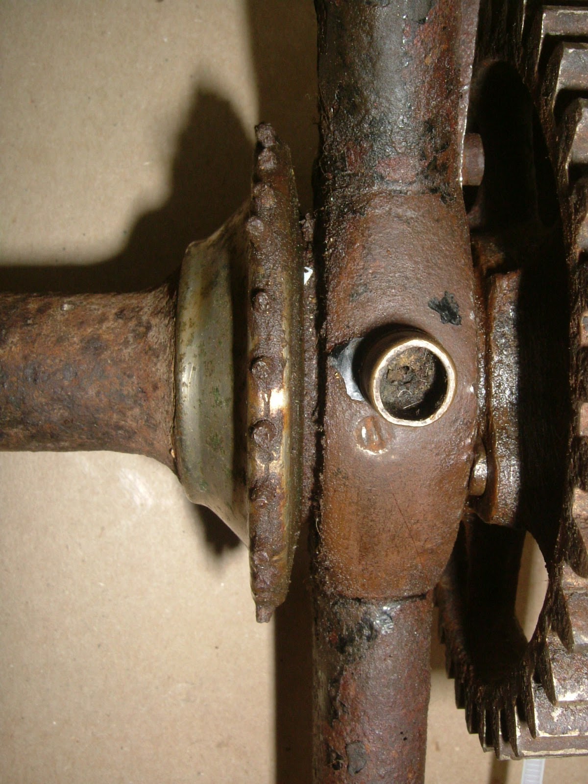
The lever pivot castings to the end of the fork legs.
The individual handlebars into the head and attaching the brake lever pivot.
I only made jigs for the handlebars and the lever pivots, the remaining assemblies being too simple to require holding, this proved to be a mistake as I'll explain later.
The handlebars and brake pivot are held in the correct locations with some very special frame building pins - old nails. unfortunately, I drilled the holes very slightly too large and the pins have a tiny amount of movement, this meant that the individual handlebars could move relative to each other and could end up not being aligned. I solved this by zip tying the bars to a thick sheet of MDF to maintain the alignment.
The lever pivot jig needed to be more complex and accurate, the pivots need to be concentric, parallel and correctly spaced relative to each other. They also need to be parallel to the main bearing housings. I recycled the old jig used to braze up the main bearings and with suitably machined spacers I was able to hold everything securely in the correct locations. I had to be careful brazing these castings as I had already had them nitrided and I didn't want to affect the hardness of the bearing surfaces. My idea was to use a large lump of steel as the spacer, this will double as a heat sink and hopefully prevent the inner races from getting too hot. I also tried a new brand of 45% silver solder this time, this has a lower melting point and should flash in quite quickly. I intended to go in quickly with a hot flame and spend as little time as possible heating the castings.
As always the first job is to thoroughly clean and degrease the surfaces to be brazed and then flux and assemble into the relevant jigs. The actual brazing went really well and the lever pivots are firmly attached and still hard after the heating. I've only cleaned up the handlebars and lever pivots so far, the saddle components have yet to be done.
For the first time I can now assemble all of the parts made to date. The sun gear still has a lot of material to be removed and the planet has nothing to attach to yet. The total weight at this point is 33lbs 14oz (~15.4kgs) which is on target as per an original.
It is great to have the basic bike together after all this time. As I mentioned before, I didn't use a jig to hold the saddle post mount and consequently it has come out at the wrong angle. It's only 5 degrees off but it will affect how and where the saddle sits and to my eye it just looks wrong, it not being parallel to the fork legs. You may remember that I wasn't completely happy with it when I machined it up. I'll make another one at some point.
Next week, I'll continue with the saddle.
In other news, we've had a little weather this week. It's been quite varied with snow on the Lindis Pass, very heavy rain on the West Coast that took away a few bridges, a tornado in Ashbuton and very hot Nor'West days like today. It's almost like we've had 4 seasons in one day or something. Hey, somebody should write a song about that.
Wednesday, 12 September 2012
Very Hot Glue Gun.
Including the 20 ball bearings, there are 33 distinct components that comprise the backbone assembly. Coincidentally, there are also 33 vertebrae in your own backbone, some of which are fused together. This shedweek I've been fusing some of my backbone pieces together. Except I used silver solder and oxy-acetylene rather than icky gooey stuff.
Here is the sequence of steps I used to stick the bits together.
Cleanliness is definitely next to Godliness when brazing joints together, all surfaces that are to be brazed need to be freshly cleaned and degreased before assembly. I tend to give the surfaces a good rub with some emery cloth and then a wipe down with a rag soaked in a suitable solvent. I used mineral turps. In my case this includes the inside of the tubes which are somewhat tricky to see into but it pays to be thorough. You need to get back to clean, fresh, shiny steel, no paint, rust or other coatings.
Shite and Briny, ready for brazing.
Then liberally apply a suitable flux for the type of braze you are using, I'm using 40% silver and I used a flux for Easy-flo No. 2 even though the solder wasn't Easy-flo. I don't know if Easy-flo is still widely available, I certainly can't get it here in NZ, I'm pretty certain that it contained cadmium and was discontinued. I would recommend staying away from solders containing cadmium. It's really not good for you. My flux came as an innocuous pot of white powder, mix this with water into a thick paste, making as much as you will use. I then just steal one of my children's paint brushes and daub the stubs and inside of the tubes and assemble.
I am going to braze the backbone into two main assemblies, the bottom half and the top half and then join the two, I'll explain why later.
I made a simple jig to hold the fork legs, rear fork crown
and fork ends in place, this is the bottom assembly.
The brazing process works by capillary action, as the joint is heated up to the melting point of the filler rod, it will suck the molten filler into the gap, A reasonably snug fit is required for this to happen, but even so, the braze can only creep so far. On the joints that have deep stubs, such as the neck/backbone, I have drilled some small (1.5mm) holes in the middle of the joint. These holes will allow me to introduce the braze farther into the joint and ensure that the joint is fully penetrated. The holes are then filled afterwards.
Silver solder melts at a much lower temperature than brass or bronze, this is important when you are joining alloy steels like chromoly that are damaged if you over cook them. When I applied the heat, I tried to keep the heat off the tube as much as possible and heated the fork end or crown instead, the tube being heated by conduction. You'll know when the joint is at temperature because the rod will just melt and flow right into the joint, if it is a large joint you can feed a whole rod in very quickly. It can be helpful to dip the end of the rod into the pot of flux. When you get near to the end of the rod and your fingers start to get hot, it is possibly to stick the remnant to the end of the new rod and carry on. With the price of silver solder only going one way, this is a skill well worth acquiring fairly early on.
I don't tend to use goggles when silver soldering since the tubes never actually get red hot only a dull red. If they are bright red then you've over cooked them, I find it easier to see this without dark goggles. It is important to keep the torch moving to prevent overheating one spot, it's a little like rubbing your tummy and patting your head at the same time. Brazing isn't rocket science but it does need practise.
The neck/backbone joint is a big one and even though I had removed all that material from inside the casting it is still a big chunk of steel to warm up. I mounted this in the vice and just waved the torch until I had the whole joint warm but not too hot and then I could focus on one part at a time to get the braze to fully penetrate, the four little holes were invaluable to get the braze right to the end of the casting.
The top assembly, the tube was left too long deliberately to
make the brazing process easier.
With the two assemblies now complete, I put the rear wheel in place and assembled the backbone into the head. Using line of sight I could then rotate the rear fork crown until I had the two wheels perfectly aligned. Mark this and drill a small hole right through the crown and the backbone. A suitable pin (a nail) is then tapped in to hold the two assemblies in the correct orientation relative to each other. This is the final joint to braze.
Pinned, Fluxed and ready for the heat...
Note how the silver solder has flowed out of the pinned hole
indicating very good penetration of the joint.
The fork legs didn't come undone as the heat didn't have time to
conduct down the legs and the remelt temperature is a little higher anyway.
Then when everything is cool, it is simply a matter of cleaning up all the joints with files and emery cloth.
The original neck...
... and my facsimile.
Note how the neck contours nicely against the
shoulder of the fork as per the original patent.
Top view. Note the filled holes along the joint, there are two visible here.
The step minus the top of the screw and the fork ends.
I can now trundle the machine around the garden and I'm pleased to report that it seems to handle like a bicycle. That may sound obvious but it means I've got the trail about right and it should have decent road manners when complete.
I had set myself a goal of having the bike sat on it's wheels inside of a year from when I started. Well, it's taken me 13 1/2 months including the 6 week museum leave, so I'm not going to complain and anyway I have no deadline since I'm only building it for myself. I don't like deadlines, apparently I get extra grumpy according to my lovely wife.
I need to have a little think about what to work on next, probably machining the lever pivot castings. Decisions, decisions.
In other news, we've had a lot of wind lately. Where I live they make a special variety of wind known locally as the Nor'Wester. It is a Foehn wind and is hot and strong, so strong that you often have to pedal downhill when riding into one. One of my favourite routes goes from my house up to Whiterock and back, it is a dead end road (unless on an MTB) and is slightly uphill all the way, it also heads off in a general N/W direction. At the weekend we had almost no wind at the house and a howling Nor'Wester just 10km up the road. The ride out was 52 minutes of grovelling into the teeth of the gale and then flying home like superman in 36 minutes. Riding uphill at 50kph is a magic feeling...
My children often come into the workshop and "borrow" my hot glue gun. When I explained what I was doing on Saturday morning, my daughter asked if the oxy-acetylene torch was a hot glue gun. Very perceptive of her really since I suppose it is a very hot glue gun.
Thursday, 30 August 2012
The Abingdon Ball Head - part 2
Spring has sprung, the grass has riz.
I wonder where the birdies is?
etc.
In stark contrast to last week, Spring appears to have been switched on at last. The birdies in the above poem (incidentally not by Spike Milligan as I always thought) being magpies. We are nearly in the attack season again, I know this because I had one shout at me last weekend, next weekend he will be dive bombing me. But I digress.
This week I have made the top lock nut for the ball head, I have chosen to make the flush variant as I won't be using a lamp bracket mounted on the head. The original I am copying does have a lamp bracket as did the Percy Nix machine in the Coventry museum. This machine was used for the 24 hour race and would certainly have required a lamp for the night time part of the event.
Now I can mount the completed neck into the head itself and establish
a) the length of the backbone to provide the correct inclination of the forks, this effects the trail of the machine and consequently how it handles.
b) the correct angle of the backbone to maintain an even gap between the wheel and the backbone. Although saying this, I have seen backbones on originals all over the place, some are very closely fitted with an even gap and some are not. Of the various originals I have now seen and measured, I have yet to see two the same, a remark echoed by other collectors that own these machines.
The angle of the forks likewise seems to vary hugely, the very early machines are more upright, something that is clear in the advertisements and literature. I've measured several from 1887 that have as little as 5 degrees inclination on the forks. This is in contrast with younger bikes that have up to 16 degrees inclination. The anomaly here is the racer from 1888 that has a full 20 degrees, this would produce a high trail value (for the period) that would be more stable at higher speeds with more rider fatigue. This is just my theory at present, I suspect it could probably be able to be ridden hands off.
As an aside I am currently reading the excellent new book on Dan Albone and Ivel cycles by Ray Miller and Lee Irvine (ISBN 978-0-9566337-4-3 available from the VCC UK). In chapter 5 Ray discusses how in 1886, Albone invented the first rear driving safety that could be ridden hands off, the discussion mentions the steering geometry being responsible but no actual mention of the trail. A friend of mine owns an 1887 Ivel safety locally (it is photographed in the book). Next time I see it, I'll measure the trail and report back. Clearly, steering geometry was beginning to be understood a little more by this time and I see no reason why Ellis & Co. wouldn't have adopted the current thinking at the time to slacken the head angle to provide more trail. I have decided to use an inclination of 16 degrees (the same as the original I am copying) which will give a moderate amount of trail.
The next job is to file the stub on the neck casting to be a very accurate fit into the backbone. I have made a little jig from part of the off cut backbone, this jig is coated with engineers blue, an evil substance that will coat everything within a 100 metre radius if children and cats are allowed into the workshop at the same time as the tube is open. The idea is that the backbone is placed into the jig and the high spots are marked by the blue, these high spots are then filed off and the process repeated. Great care being taken not to twist the casting relative to the jig. This took many hours, but the care has paid off and I now have a very well fitting backbone that should braze easily.
The final job is to hollow out the stubs for all the reasons previously stated.
At last we can now do a dry assembly to see how it all fits together.
Still to do on the backbone is to make the step which is a simple folded piece of steel brazed to the left fork leg. I also need to drill and tap the holes in the rear fork crown to allow a mudguard to be mounted.
In other news, I have promised my lovely wife that I will build her a new deck when spring arrives. I fear that my shed fettling will have to take a back seat for a period if this good weather continues. I did try to bribe my brother to come and build it but he pretended not to hear me.
I wonder where the birdies is?
etc.
In stark contrast to last week, Spring appears to have been switched on at last. The birdies in the above poem (incidentally not by Spike Milligan as I always thought) being magpies. We are nearly in the attack season again, I know this because I had one shout at me last weekend, next weekend he will be dive bombing me. But I digress.
This week I have made the top lock nut for the ball head, I have chosen to make the flush variant as I won't be using a lamp bracket mounted on the head. The original I am copying does have a lamp bracket as did the Percy Nix machine in the Coventry museum. This machine was used for the 24 hour race and would certainly have required a lamp for the night time part of the event.
This is a photo of the bike taken in or prior to 1931 (when it was in the Sammy Bartleet collection)
and the lamp bracket is clearly visible. From Bartleet's Bicycle Book, 1931
The bracket has now disappeared as in this photograph I took just a few months ago of the same machine.
But this is what the flush variant looks like, neat eh?
The Upper example is an early geared facile and the lower is a non geared model, both by Ellis & Co.
Machining the lock nut just involved simple turning and screw cutting
plus a little indexing to get the holes in the correct place.
Now I can mount the completed neck into the head itself and establish
a) the length of the backbone to provide the correct inclination of the forks, this effects the trail of the machine and consequently how it handles.
b) the correct angle of the backbone to maintain an even gap between the wheel and the backbone. Although saying this, I have seen backbones on originals all over the place, some are very closely fitted with an even gap and some are not. Of the various originals I have now seen and measured, I have yet to see two the same, a remark echoed by other collectors that own these machines.
The angle of the forks likewise seems to vary hugely, the very early machines are more upright, something that is clear in the advertisements and literature. I've measured several from 1887 that have as little as 5 degrees inclination on the forks. This is in contrast with younger bikes that have up to 16 degrees inclination. The anomaly here is the racer from 1888 that has a full 20 degrees, this would produce a high trail value (for the period) that would be more stable at higher speeds with more rider fatigue. This is just my theory at present, I suspect it could probably be able to be ridden hands off.
As an aside I am currently reading the excellent new book on Dan Albone and Ivel cycles by Ray Miller and Lee Irvine (ISBN 978-0-9566337-4-3 available from the VCC UK). In chapter 5 Ray discusses how in 1886, Albone invented the first rear driving safety that could be ridden hands off, the discussion mentions the steering geometry being responsible but no actual mention of the trail. A friend of mine owns an 1887 Ivel safety locally (it is photographed in the book). Next time I see it, I'll measure the trail and report back. Clearly, steering geometry was beginning to be understood a little more by this time and I see no reason why Ellis & Co. wouldn't have adopted the current thinking at the time to slacken the head angle to provide more trail. I have decided to use an inclination of 16 degrees (the same as the original I am copying) which will give a moderate amount of trail.
The next job is to file the stub on the neck casting to be a very accurate fit into the backbone. I have made a little jig from part of the off cut backbone, this jig is coated with engineers blue, an evil substance that will coat everything within a 100 metre radius if children and cats are allowed into the workshop at the same time as the tube is open. The idea is that the backbone is placed into the jig and the high spots are marked by the blue, these high spots are then filed off and the process repeated. Great care being taken not to twist the casting relative to the jig. This took many hours, but the care has paid off and I now have a very well fitting backbone that should braze easily.
The jig to mark the high spots on the casting,
shortly before engineers blue covered everything.
File off the marked high spots and repeat. Carefully.
Eventually, an accurate fit is obtained.
The backbone can now be cut to length.
A little trigonometry to ensure the forks are inclined at the correct angle before any cutting takes place.
Ensure that both wheels are on a horizontal surface and the above chart is taped vertically
to the wall behind the bike, then simply line up the forks with the chosen angle by line of sight.
Measure twice, cut once.
The tube has been left slightly proud of the edge to assist in the brazing process.
It will be filed flush afterwards.
The final job is to hollow out the stubs for all the reasons previously stated.
At last we can now do a dry assembly to see how it all fits together.
Still to do on the backbone is to make the step which is a simple folded piece of steel brazed to the left fork leg. I also need to drill and tap the holes in the rear fork crown to allow a mudguard to be mounted.
In other news, I have promised my lovely wife that I will build her a new deck when spring arrives. I fear that my shed fettling will have to take a back seat for a period if this good weather continues. I did try to bribe my brother to come and build it but he pretended not to hear me.
Wednesday, 15 February 2012
Bearing Adjustment Locks
Cleaned up silver soldered joints, the head will be plated later
and these require a little more work.
The depth is not super critical but I didn't want to
break through the tube wall so I had to be careful here.
The brazed joints all cleaned up easily but doing so showed up a slight movement in the non gear side bearing housing. This has clearly happened as a result of the heat, the housing are now not quite parallel. The discrepancy is very slight and doesn't seem to affect the bearing (I built it up to check) which is good because the chances of cold setting the 4130 forks is effectively nil, they are very strong.
I also drilled and tapped the holes for the oiler and inner bearing race locking grub screw (2BA & 4BA respectively). On the original these holes were very close. too close I thought so I cross referenced with some pictures I took of the racer in the Coventry Transport Museum. This famous machine has the oiler hole located much higher up and away from the grub screw, I have done the same and based mine upon the Percy Nix bike in Coventry.
The original facile I am copying has very close
holes for the oiler and inner race grub screw.
The holes on Percy Nix's racing machine are farther apart.
I've based mine upon the Coventry machine.
A good view of the grub screw and the oiler in place.
The Coventry bike is missing it's oilers, this oiler is missing it's cover.
They're tricky little things, the inner edge is a curved 45 degree bevel
and then two notched are filed into this to produce three teeth
to lock into the castellations on the outer bearing race.
My stock of 4BA cheese head screws is a little low,
hence the rusty one used in the picture.
BA screws are all but unobtainable for sensible money in NZ
so I'll either make or import some myself.
Next week I'll hack into a large chunk of Gunmetal (LG2 bronze) and start the spoke flanges for both wheels. Gunmetal machines beautifully so I'm really looking forward to this.
In other news my parents, both keen gardeners, have been busy in our garden. When we moved in many years ago we found an old greenhouse hidden in one corner of the garden. My parents have now dismantled this to allow us to move the compost bin to somewhere where it may actually work. My father has about a dozen greenhouses himself but I'm unsure how he's going to fit mine into his suitcase when he leaves. I'm sure he'll try.
An amusing incident happened at dinner the other night, the children were running through all the languages that they knew how to say hello in. After the obvious English, French, German, Spanish, Maori & Japanese, my daughter upped the ante with Gaelic. "Pogue Mahone" she proudly said. I nearly spat my tea all over the table, having shared a house with a native Gaelic speaker at University I happened to know what this very useful phrase actually means. I suspect that an unknown Irishman has been having a little fun at the expense of my Daughters teacher. Apparently the class all solemnly repeat the phrase in that special monotone that children the world over reserve for "Good Morning Teacher". My daughter was very embarrassed when I told her what it meant, whilst my son was busy writing it down. My parents were not amused in that very Victorian manner.
Thursday, 9 February 2012
Brazing the Front Forks
As promised last time, I've been directing my efforts at getting the front forks brazed up. There seemed to be an endless list of things to do before I could light up the oxy-acetylene though. I needed to hollow out the stubs that extend into each of the tubes. As mentioned before this is for several reason, firstly it helps to prevent cracks forming at the junction of the stub and the tube. Secondly it makes the brazing process easier as a large mass of material that is hard to heat is removed, this helps to prevent overcooking the tubes. And last is the obvious weigh loss from removing metal. In this case, hollowing out the 6 stubs (2 per 'knee' and 2 on the head) removed a pound of weight (0.45kg). Not insignificant.
However before I hollow out the stubs, I need to stamp the top of the Abingdon Ball Head with the appropriate patent information. I need the stubs to be solid to support the hammer blows required to do this. I admit to putting this task off for ages, the potential to completely screw it up is high. Every now and again I'd have a little practise on some scrap until I had developed a method of working that reduced the chance of errors. I was still shaking when I struck every letter and number though. The hard bit is to get the individual letters to be correctly aligned vertically with respect to each other and correctly spaced. My method is simple, I use 4 layers of masking tape to define the lower edge of each letter or number, placing each stamp onto the surface of the workpiece and then sliding until it contacts the ridge of masking tape. With practise, it becomes easier to apply the same pressure against the tape and the letters then line up with each other. To get the spacing correct, I mark the tape ridge at the correct intervals and then line up each stamp with the next mark.
With this onerous chore out of the way I can now hollow out the stubs. I very roughly drilled and milled out as much material as possible before getting stuck in with a carbide burr mounted in an air die grinder. I bought a cheap Chinese die grinder that will run at 25,000 rpm without over running my compressor too much. Think of a dentist's drill on steroids. You really do need those high rpms when removing steel. It is a truly horrible job and results in thousands and thousands of razor sharp needles of steel *everywhere*, regardless of how carefully everything else is covered up. I've been digging steel splinters out of my fingers (and feet!) ever since despite wearing a ridiculous amount of PPE.
Now I need to make a jig to hold everything in the correct location whilst the heat is applied.
I used 40% silver solder to keep the heat on the 4130 chromoly tubing down. Silver solder has suddenly got really expensive, still I only need the one kidney. It all appears to have been successful with good penetration into the joints and very little distortion from the heat, although one of the blanks in the bearing house was *very* hard to get out afterwards. Fortunately I had previously made a 1.75" x 26tpi tap and had it hardened for exactly this eventuality and I was able to clean out the threads nicely.
This week I'll clean up the joints and mill the slots for the locking tabs. Then I can continue with the gunmetal flanges. Then I can make the spokes... etc. I've set myself a goal of having the frame sat on it's wheels inside of a year. I'm already 6 months into the project and more or less on track.
In other news, I've finally managed to arrange a small aftershock for my parents, We were having dinner in Christchurch and were rudely interrupted by a vicious little 4.6, I don't think they liked it much. We also had a nasty little swarm last night but fortunately my parents are away on a tiki tour of the West Coast this week. I'll try and save a few for their return.
In more other news, someone seems to have stolen summer this year. We haven't had one yet, does anyone know where it is?
However before I hollow out the stubs, I need to stamp the top of the Abingdon Ball Head with the appropriate patent information. I need the stubs to be solid to support the hammer blows required to do this. I admit to putting this task off for ages, the potential to completely screw it up is high. Every now and again I'd have a little practise on some scrap until I had developed a method of working that reduced the chance of errors. I was still shaking when I struck every letter and number though. The hard bit is to get the individual letters to be correctly aligned vertically with respect to each other and correctly spaced. My method is simple, I use 4 layers of masking tape to define the lower edge of each letter or number, placing each stamp onto the surface of the workpiece and then sliding until it contacts the ridge of masking tape. With practise, it becomes easier to apply the same pressure against the tape and the letters then line up with each other. To get the spacing correct, I mark the tape ridge at the correct intervals and then line up each stamp with the next mark.
It is worth noting that letters or numbers with less area, such as I and 1, require a lighter blow
other wise they appear over struck compared to larger letters.
The results aren't too bad although the I is too far to the right,
I'm not too bothered as the original is also clearly hand stamped.
With this onerous chore out of the way I can now hollow out the stubs. I very roughly drilled and milled out as much material as possible before getting stuck in with a carbide burr mounted in an air die grinder. I bought a cheap Chinese die grinder that will run at 25,000 rpm without over running my compressor too much. Think of a dentist's drill on steroids. You really do need those high rpms when removing steel. It is a truly horrible job and results in thousands and thousands of razor sharp needles of steel *everywhere*, regardless of how carefully everything else is covered up. I've been digging steel splinters out of my fingers (and feet!) ever since despite wearing a ridiculous amount of PPE.
Roughly removing as much material as possible...
...before getting the carbide burr out
A pound of steel was removed from these 6 stubs.
Now I need to make a jig to hold everything in the correct location whilst the heat is applied.
I happened to have some angle iron in my magic cupboard, so this got chopped up...
...and with some 10mm threaded rod, I can locate all the bits in a frame that doesn't move.
I used 40% silver solder to keep the heat on the 4130 chromoly tubing down. Silver solder has suddenly got really expensive, still I only need the one kidney. It all appears to have been successful with good penetration into the joints and very little distortion from the heat, although one of the blanks in the bearing house was *very* hard to get out afterwards. Fortunately I had previously made a 1.75" x 26tpi tap and had it hardened for exactly this eventuality and I was able to clean out the threads nicely.
This week I'll clean up the joints and mill the slots for the locking tabs. Then I can continue with the gunmetal flanges. Then I can make the spokes... etc. I've set myself a goal of having the frame sat on it's wheels inside of a year. I'm already 6 months into the project and more or less on track.
In other news, I've finally managed to arrange a small aftershock for my parents, We were having dinner in Christchurch and were rudely interrupted by a vicious little 4.6, I don't think they liked it much. We also had a nasty little swarm last night but fortunately my parents are away on a tiki tour of the West Coast this week. I'll try and save a few for their return.
In more other news, someone seems to have stolen summer this year. We haven't had one yet, does anyone know where it is?
Saturday, 28 January 2012
Harden the four cup(s) *
I've been able to get out in the shed a little this week. Enough to fettle the rear hub from a bar of 4140. When I checked the drawings I had made back in 2008, I was certain that I'd made a mistake measuring the original and that I'd got the dimensions too small. I even checked a couple of 1890's front wheels I have lying around which confirmed that the measurements were correct. The bearings seemed tiny when compared with the large front wheel bearings, but are exactly comparable with a modern front wheel.
The first task is to make the hub shell, this uses the same techniques as in the front hub just on a smaller scale and with fewer bearing surfaces (!). There is no need to mill key ways to lock the gunmetal flanges in place since the rear hub transmits no torque. In practise I have found that the spoke tension will adequately hold the flanges in place, however I will either make them an interference fit or soft solder them on as was the norm back in the day. The oiler hole is tapped at 2BA, I'm happy using BA threads since they were first formulated in the 1880's and I have previously found them on antique bikes.
The next job is to make the cones, the fixed (right) cone is left smooth but the adjustable (left) cone is knurled with a straight, fine pattern. My knurling tool has diamond pattern wheels and with the shocking local price of replacement wheels, I've milled 80 'knurls' instead of rolling them.
I've calculated a formula for the dimensions of the race based upon the number and size of balls required, this has worked out well so far although the formula leaves no room for a gap in the balls which they need. You can either add one to the number of balls (n) or just add a smidgeon to the calculated value D. I have found that making D larger by 0.020" or so is enough to get a useful gap. The calculated value for D in the rear hub = 0.1875/sin(180/11) + 0.1875 = 0.853". In practise I machined it to 0.875" and have a sufficient gap, as can be seen in the above photo, so the balls don't bind.
With all the steel components of the hubs now complete, I can get them heat treated. I initially chose 4140 steel because of it's suitability for nitriding which produces a very hard surface case up to Rc 64 but retains the tough centre. Nitriding will also cause far less distortion due to the lower heat required. SSM have a local office so I gave them a ring in the morning and was told that if I can get the parts to them by 10 o'clock they could put them in today's batch and I could pick them up in the afternoon. A fantastic service, I'm sure you'll agree.
In other news my parents are now here and are pleased that I've been unable to organise any large aftershocks so far. My Dad is being kind to me and has only offered advice on using the dividing head to date. He sits on the stool in the corner of the workshop like a benevolent owl. I'm going to try and get the forks brazed up whilst he's here. He has far more experience than me at brazing, so I'll get him to do it and then I can examine his work. This will be the focus of my shed time next week.
We had a huge electrical storm at the weekend, It passed directly over our house and we suffered a very close lightening strike. Had I any hair remaining I'm certain it would have stood on end from the electrickery. My wife's new computer (birthday present) had it's motherboard fried and we are trying to arrange a repair on insurance. What fun. In the meantime I've resurrected an ancient steam powered computer to allow us to access the interweb and me to continue posting this nonsense.
* with apologies to Chopper Reid
The first task is to make the hub shell, this uses the same techniques as in the front hub just on a smaller scale and with fewer bearing surfaces (!). There is no need to mill key ways to lock the gunmetal flanges in place since the rear hub transmits no torque. In practise I have found that the spoke tension will adequately hold the flanges in place, however I will either make them an interference fit or soft solder them on as was the norm back in the day. The oiler hole is tapped at 2BA, I'm happy using BA threads since they were first formulated in the 1880's and I have previously found them on antique bikes.
The next job is to make the cones, the fixed (right) cone is left smooth but the adjustable (left) cone is knurled with a straight, fine pattern. My knurling tool has diamond pattern wheels and with the shocking local price of replacement wheels, I've milled 80 'knurls' instead of rolling them.
Roughing out one of the cones
Parting it off.
Machining the outside face.
Milling the 'knurls'
The hub spins beautifully on it's 11 x 3/16" balls in either race.
I've calculated a formula for the dimensions of the race based upon the number and size of balls required, this has worked out well so far although the formula leaves no room for a gap in the balls which they need. You can either add one to the number of balls (n) or just add a smidgeon to the calculated value D. I have found that making D larger by 0.020" or so is enough to get a useful gap. The calculated value for D in the rear hub = 0.1875/sin(180/11) + 0.1875 = 0.853". In practise I machined it to 0.875" and have a sufficient gap, as can be seen in the above photo, so the balls don't bind.
With all the steel components of the hubs now complete, I can get them heat treated. I initially chose 4140 steel because of it's suitability for nitriding which produces a very hard surface case up to Rc 64 but retains the tough centre. Nitriding will also cause far less distortion due to the lower heat required. SSM have a local office so I gave them a ring in the morning and was told that if I can get the parts to them by 10 o'clock they could put them in today's batch and I could pick them up in the afternoon. A fantastic service, I'm sure you'll agree.
The parts were still warm when I picked them up,
like fresh hot cross buns straight out of the oven, only not as tasty.
And a bit harder.
In other news my parents are now here and are pleased that I've been unable to organise any large aftershocks so far. My Dad is being kind to me and has only offered advice on using the dividing head to date. He sits on the stool in the corner of the workshop like a benevolent owl. I'm going to try and get the forks brazed up whilst he's here. He has far more experience than me at brazing, so I'll get him to do it and then I can examine his work. This will be the focus of my shed time next week.
We had a huge electrical storm at the weekend, It passed directly over our house and we suffered a very close lightening strike. Had I any hair remaining I'm certain it would have stood on end from the electrickery. My wife's new computer (birthday present) had it's motherboard fried and we are trying to arrange a repair on insurance. What fun. In the meantime I've resurrected an ancient steam powered computer to allow us to access the interweb and me to continue posting this nonsense.
* with apologies to Chopper Reid
Subscribe to:
Comments (Atom)


